EP0891787A2 - Physical training machine with attitude adjustement - Google Patents
Physical training machine with attitude adjustement Download PDFInfo
- Publication number
- EP0891787A2 EP0891787A2 EP98830399A EP98830399A EP0891787A2 EP 0891787 A2 EP0891787 A2 EP 0891787A2 EP 98830399 A EP98830399 A EP 98830399A EP 98830399 A EP98830399 A EP 98830399A EP 0891787 A2 EP0891787 A2 EP 0891787A2
- Authority
- EP
- European Patent Office
- Prior art keywords
- posture
- physical training
- user
- rod
- exercise
- Prior art date
- Legal status (The legal status is an assumption and is not a legal conclusion. Google has not performed a legal analysis and makes no representation as to the accuracy of the status listed.)
- Granted
Links
Images

Classifications
-
- A—HUMAN NECESSITIES
- A63—SPORTS; GAMES; AMUSEMENTS
- A63B—APPARATUS FOR PHYSICAL TRAINING, GYMNASTICS, SWIMMING, CLIMBING, OR FENCING; BALL GAMES; TRAINING EQUIPMENT
- A63B21/00—Exercising apparatus for developing or strengthening the muscles or joints of the body by working against a counterforce, with or without measuring devices
- A63B21/15—Arrangements for force transmissions
- A63B21/151—Using flexible elements for reciprocating movements, e.g. ropes or chains
- A63B21/154—Using flexible elements for reciprocating movements, e.g. ropes or chains using special pulley-assemblies
- A63B21/156—Using flexible elements for reciprocating movements, e.g. ropes or chains using special pulley-assemblies the position of the pulleys being variable, e.g. for different exercises
-
- A—HUMAN NECESSITIES
- A63—SPORTS; GAMES; AMUSEMENTS
- A63B—APPARATUS FOR PHYSICAL TRAINING, GYMNASTICS, SWIMMING, CLIMBING, OR FENCING; BALL GAMES; TRAINING EQUIPMENT
- A63B23/00—Exercising apparatus specially adapted for particular parts of the body
-
- A—HUMAN NECESSITIES
- A63—SPORTS; GAMES; AMUSEMENTS
- A63B—APPARATUS FOR PHYSICAL TRAINING, GYMNASTICS, SWIMMING, CLIMBING, OR FENCING; BALL GAMES; TRAINING EQUIPMENT
- A63B21/00—Exercising apparatus for developing or strengthening the muscles or joints of the body by working against a counterforce, with or without measuring devices
- A63B21/06—User-manipulated weights
- A63B21/062—User-manipulated weights including guide for vertical or non-vertical weights or array of weights to move against gravity forces
- A63B21/0626—User-manipulated weights including guide for vertical or non-vertical weights or array of weights to move against gravity forces with substantially vertical guiding means
- A63B21/0628—User-manipulated weights including guide for vertical or non-vertical weights or array of weights to move against gravity forces with substantially vertical guiding means for vertical array of weights
-
- A—HUMAN NECESSITIES
- A63—SPORTS; GAMES; AMUSEMENTS
- A63B—APPARATUS FOR PHYSICAL TRAINING, GYMNASTICS, SWIMMING, CLIMBING, OR FENCING; BALL GAMES; TRAINING EQUIPMENT
- A63B2225/00—Miscellaneous features of sport apparatus, devices or equipment
- A63B2225/09—Adjustable dimensions
-
- A—HUMAN NECESSITIES
- A63—SPORTS; GAMES; AMUSEMENTS
- A63B—APPARATUS FOR PHYSICAL TRAINING, GYMNASTICS, SWIMMING, CLIMBING, OR FENCING; BALL GAMES; TRAINING EQUIPMENT
- A63B2225/00—Miscellaneous features of sport apparatus, devices or equipment
- A63B2225/09—Adjustable dimensions
- A63B2225/093—Height
Definitions
- the present invention relates to a physical training machine with attitude adjustment, i.e. a physical training machine whose attitude can be varied according to the anthropometric characteristics of the user and/or to the exercises the user is to perform on the machine.
- the latter comprise a basic frame whereto are associated means for imparting a force by the user, such as a bar or handles or levers, connected to a load which provides a resistance to the imparted force.
- the user is positioned on a seat or anyway on a support (for instance a bench, a saddle or other supports) and from this position he/she performs a series of exercises aimed at the type of sporting or rehabilitative activities carried out.
- a support for instance a bench, a saddle or other supports
- the seat can be adjusted, for instance in height, by the user to modify suitably the distances between seat and bar or handles.
- Such adjustment is essentially manual and it needs to be performed each time in correspondence with a change of exercise or with a change of user.
- an activating device usually a pedal, able to arm the machine.
- such machines comprise an implement portion, provided with bars, dumb-bells, or similar means for imparting a force, connected to a mass defining the resistance offered by the machine.
- the user's interaction with the implement portion i.e. the user's gripping such means, is subordinated to the activation of the aforesaid pedal device which brings, thanks to the force imparted by the user on the pedal itself, the implement portion from a waiting position to an exercise position, wherein the user can grip the dumb-bell, the handles or the other similar means.
- a drawback of machines comprising this type of pedal device relates to the fact that such device is essentially set fixedly, on a standard position essentially corresponding to a user of "average" height; in practice, regardless of the user's height, the pedal device is set in the same way: this can cause inappropriate movements by the persons who do not fall within the dimensional characteristics whereon the device is designed. In any case, regardless of the user's height, it is possible for the athlete's approach to the machine to be found uncomfortable due to the impossibility of performing the aforesaid adjustments.
- the object of the present invention therefore is to eliminate the aforementioned drawbacks with a physical training machine which allows to position the machine in its configuration best suited for the execution of an exercise in an essentially automatic manner, using appropriate control organs provided on the machine itself, able to be activated directly by the user (or by an instructor or another person so tasked) and able to position in an automatic manner a portion of the physical training machine in correspondence with the positioning of another portion of the machine itself.
- the positioning of a first portion of the machine results from the positioning performed on another portion of the machine, appropriately connected to the first; in practice, at least two portions of the machine are mutually constrained by a kinematic connection which, as a result of the displacement of a first portion, determines the displacement of at least a second portion connected to the first.
- the movement of the first portion, or main movement can be interlocked to motorisation means (comprising, for instance, an electric motor positioned in correspondence with the seat) which, moving the first portion, thereby position the second one, whose motion thus is a function of the movement of the first one.
- motorisation means comprising, for instance, an electric motor positioned in correspondence with the seat
- the physical training machine 1 with attitude adjustment comprises at least one posture portion 2 and one implement portion 3 and 4, described hereafter.
- the physical training machine comprises a base structure 1' able to support the aforesaid posture and implement portions.
- the posture portion comprises a seat 20, provided with a backrest 21 and supported by a support structure 22.
- the base structure 1' of the physical training machine I presents a part 11 of its own frame essentially vertical and slightly inclined obliquely; on this portion 11 is constrained the support structure 22 of the seat, able to slide on two guides 23 which are parallel to each other and to the portion 11.
- the guides 23 can be fastened to the portion 11 of the structure 1' through fastening means comprising devices of the type called "silent block” and indicated with 23s, in order to make less rigid the coupling between the guides 23-support 22-seat 20 set and the base structure 1' and thereby to improve sliding by the seat along the guides 23.
- the seat 20 can be moved vertically (directions V1 and V2 in Figure 1) along the guides 23 and by means of coupling cylinders and pulleys 23c, thanks to motorisation means 6 which can comprise, for instance, an electric motor acting on a worm screw connected on the support structure 22.
- motorisation means 6 can comprise, for instance, an electric motor acting on a worm screw connected on the support structure 22.
- the motorisation of the seat 20 allows to vary the relative distance between the posture portion 2 and implement portion 3, 4 of the machine, according to the user's anthropometric values, to the exercise to be performed, etc.
- motorisation can be provided on another portion of the machine, allowing, in any case, suitably to vary the relative distance between the aforesaid posture and implement portions.
- the implement portion 3, 4 comprises action means 30, suitable for the execution of the exercise and comprising, for instance, handles, levers, bars or the like, connected to an element 9 able to provide a resistance.
- the resistance element 9 is of the gravitational type and it is represented by the so-called "weight pack", i.e. by a series of brick-shaped weights 90 sliding in related guides 91 and connected, through appropriate transmissions 93 to the implement portion 3.
- the implement portion 3 always with reference to the accompanying non-limiting figures, comprises two grip handles 30 supported by two angled arms 34 acting on corresponding pulleys 33 connected to the resistance element 9, through known cable 93f.
- the implement portion 3, 4 further comprises means 4 for activating the action means 30, able to set the action means in a configuration suitable for the execution of an exercise, i.e. able to bnng the action means themselves into a grip position reachable by the user.
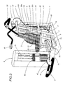
- Figure 2 shows a waiting configuration, wherein the action means 30 are positioned at such a height from the seat 20 as not to be easily reachable by the user.
- Figure 3 instead, shows the configuration assumed by the machine 1 after the (downward) action of the activation means 4, which place the handles 30 in a lowered position and make it accessible for the exercise.
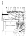
- the activation means 4 comprise a footrest 41, pivoting, in one of its ends, around a horizontal axis 77 and provided with an organ shaped as a circle portion 42 or winder, whereto is fastened one end of a cable 5, whose remaining end is fastened to a corresponding part of the action means 30 to activate the same, i.e. to bring the related arms 34 and the related handles in a position reachable by the user.
- the footrest 41 rotating around the axis 77 as a result of a pressure thereon imparted with direction T2 by the athlete, determines a corresponding displacement of the cable 5, able to "arm" the action means 30.
- the footrest in order to allow a correct utilisation of the machine, i.e. to be activated without erroneous movements, must be separated from the seat by a value that varies according to the dimensions of the person.
- the activation means 4 are interlocked to the motion imparting means 6 which act on the seat 20 and are displaced as a result.
- the ratio between the displacement of the seat 20 (vertical V1-V2) and the displacement of the footrest 41 in height must be correlated to the ratios which are functions of the anthropometric dimensions of the standard athletes, it is possible to connect the two portions of the machine kinematically, in order to obtain automatically the correct positioning between seat and footrest.
- the particular connection (indicated as 7 in its entirety) used in the embodiment shown shall now be described in detail, without thereby limiting other possible realisations of the physical training machine with attitude adjustment constituting the subject of the invention.
- a first rod 70 fastened, in a first end, to a projection 22h of the support structure 22 through a pin 80, in order to follow the support structure 22 itself in the upward movement V1 or downward movement V2.
- the first rod 70 is hinged to a first lever 71, L-shaped and pivoting, in its junction portion, around a second pin 79, fixed with respect to the base structure 1'.
- the first lever 71 is connected, in its first end, in 71a, to the second end of the first rod 70.
- a clockwise rotation R1 occurs of the first lever 71 around the pin 79, whilst for a downward displacement V2, the rotation shall be counter-clockwise R2.
- a first end of a second rod 72 which, in the example shown is positioned nearly horizontally.
- the clockwise rotation R1 of the first lever 71 shall determine a displacement F1 of the second rod 72 towards the footrest 41, vice versa
- a counter-clockwise rotation R2 shall determine a displacement F2 away from the footrest 41.
- a second lever 73 To the second end of the second rod 72 is pivoted, in 72a, a second lever 73.
- the second lever 73 is pivoted around a third pin 78, fixed with respect to the base structure 1'.
- the second lever 73 is rigidly connected (i.e. it constitutes a single body) with a third rod 74 positioned opposite to the fulcrum 78 and serving as a support base for the footrest 41.
- a displacement in direction Fl of the second rod 72 determines a clockwise rotation S1 of the second lever 73 and of the base 74, whilst a displacement F2 determines a counter-clockwise rotation S2 thereof.
- the third rod 74 is positioned lowered (as shown in Figure 1 in continuous lines) in correspondence with the maximum lowered position of the seat, whilst it will be raised (as shown schematically in dashed lines), when the height of the seat is raised.
- V1-R1-F1 to displacements performed upstream corresponds a positioning of the footrest 41 itself in a configuration derived from the positioning of the posture portion 2.
- the rotation of the footrest 41 allows, as stated previously, the activation of the implement portion 3; in correspondence with the third pivot 78 a device for the correction of the backlash can be provided, comprising in the example simply an idle roller 100 integral with the rod 74, able to compensate for the displacement of the footrest following the motion of the seat 20, thereby determining no changes in its modes of activation of the action means 30.
Abstract
Description
- Figure 1 shows, in a schematic side view, with some parts removed to highlight others, a possible embodiment of a physical training machine in accordance with the present invention;
- Figures 2, 3 show, in a perspective schematic view, the embodiment as per Figure 1, in two different configurations.
Claims (8)
- Physical training machine (1) with attitude adjustment, of the type comprising at least a posture portion (2) and an implement portion (3; 4); said posture portion (2) being provided with means (20) able to allow the positioning of a user in an exercise configuration wherein the user him/herself is set to execute a physical training exercise; said implement portion (3; 4) being provided with action means (30), accessible to said user when he/she is positioned in exercise configuration and employable by him/her for the application of a force able to contrast, for the execution of said exercise, a resistance offered by the physical fitness machine; physical fitness machine (1) characterised in that it comprises:means (6) for adjusting the relative position between said posture portion (2) and said implement portion (3; 4) acting on one thereof;connecting means (7), positioned and acting between said posture (2) and implement (3; 4) portions able to modify the position of one of said portions as derived from the change in position of the other one of said portions.
- Physical training machine according to claim 1, wherein said implement portion (3; 4) comprises means (4) for activating said action means (30), able to set the action means themselves in a configuration suitable for the execution of an exercise, i.e. able to bring the action means themselves in a position reachable by said user, characterised in that said connecting means (7) are positioned and acting between said posture portion (2) and said activation means (4).
- Machine according to claim 2, characterised in that said connecting means (7) comprise mechanical means for the transmission of motion.
- Machine according to claim 2, characterised in that said connecting means (7) comprise a plurality of levers or rods (70, 71, 73) mutually constrained in such a way as to transduce, with a given transmission ratio, the motion related to a displacement of said posture portion (2) into a displacement of said activation means (4).
- Machine according to claim 4, wherein said activation means (4) comprise a footrest (41) pivoted on a first axis (77), characterised in that said posture portion comprises a support structure (22) for said user, movable with respect to a base structure (1') through said adjustment means (6) and said connecting means (7) comprise: a first rod (70), fastened in a first end to said support structure (22); a first lever (71), with its fulcrum around a second pin (79) fixed with respect to said base structure (1') and connected, in its first end, to the second end of said first rod (70); a second rod (72), fastened in its first end to a second end of said first lever (71); a second lever (73 ), fastened to the second end of said second rod (72) and with its fulcrum around a third pin (78) fixed with respect to said base structure (1'), and connected to said footrest (41) through a third rod (74) supporting the same, angularly positioned with respect to said second lever (73) in such a way as to make the displacements executed upstream on said posture portion, correspond to a rotation of said third rod (74) suitable to position said footrest (41) in a configuration derived from the positioning of said posture portion (2).
- Physical training machine according to claim 1, characterised in that said means (6) for adjusting the relative position are motorised.
- Physical training machine according to claim 1, characterised in that said adjustment means (6) are positioned and acting at least in correspondence with said posture portion (2).
- Physical training machine according to claim 7, wherein said posture portion comprises at least one seat (20), characterised in that said motorised adjustment means (6) comprise motion imparting means able to translate bidirectionally said seat at least along a direction of approach to said implement portion (3).
Applications Claiming Priority (2)
| Application Number | Priority Date | Filing Date | Title |
|---|---|---|---|
| ITBO970427 | 1997-07-15 | ||
| IT97BO000427A IT1293242B1 (en) | 1997-07-15 | 1997-07-15 | GYMNASIAN MACHINE WITH STRUCTURE ADJUSTMENT. |
Publications (3)
| Publication Number | Publication Date |
|---|---|
| EP0891787A2 true EP0891787A2 (en) | 1999-01-20 |
| EP0891787A3 EP0891787A3 (en) | 1999-03-17 |
| EP0891787B1 EP0891787B1 (en) | 2003-10-01 |
Family
ID=11342401
Family Applications (1)
| Application Number | Title | Priority Date | Filing Date |
|---|---|---|---|
| EP98830399A Expired - Lifetime EP0891787B1 (en) | 1997-07-15 | 1998-07-01 | Physical training machine with attitude adjustment |
Country Status (7)
| Country | Link |
|---|---|
| US (1) | US6132347A (en) |
| EP (1) | EP0891787B1 (en) |
| BR (1) | BR9802448A (en) |
| CA (1) | CA2243036A1 (en) |
| DE (1) | DE69818564T2 (en) |
| ES (1) | ES2207808T3 (en) |
| IT (1) | IT1293242B1 (en) |
Cited By (1)
| Publication number | Priority date | Publication date | Assignee | Title |
|---|---|---|---|---|
| WO2004014493A1 (en) * | 2002-07-28 | 2004-02-19 | Sonja Stromberg | Profile for frames of fitness and health machines |
Families Citing this family (14)
| Publication number | Priority date | Publication date | Assignee | Title |
|---|---|---|---|---|
| IT1321285B1 (en) * | 2000-06-06 | 2004-01-08 | Panatta Sport Srl | MACHINE TO EDUCATE A USER TO MAINTAIN A CORRECT POSTURE. |
| ITCZ20040001A1 (en) * | 2004-01-26 | 2004-04-26 | Salvatore Carbone | GYMNASTIC TOOL FOR TRAINING OF PECTORAL, DELTOID, TRAPEZI AND TRICEPS MUSCLES |
| US20080039296A1 (en) * | 2006-08-14 | 2008-02-14 | Zeev Steinmetz | Method and device to enable and assist the elderly and females to exercise their leg and chest muscles |
| US7892147B2 (en) * | 2007-08-31 | 2011-02-22 | Vick Jr Richard N | Abdominal exercise device with alarm |
| EP2488262B1 (en) | 2009-10-16 | 2014-07-16 | Douglas Dorsay | Exercise device and method |
| US9254409B2 (en) | 2013-03-14 | 2016-02-09 | Icon Health & Fitness, Inc. | Strength training apparatus with flywheel and related methods |
| WO2015100429A1 (en) | 2013-12-26 | 2015-07-02 | Icon Health & Fitness, Inc. | Magnetic resistance mechanism in a cable machine |
| US10426989B2 (en) | 2014-06-09 | 2019-10-01 | Icon Health & Fitness, Inc. | Cable system incorporated into a treadmill |
| US10940360B2 (en) | 2015-08-26 | 2021-03-09 | Icon Health & Fitness, Inc. | Strength exercise mechanisms |
| TWI644702B (en) | 2015-08-26 | 2018-12-21 | 美商愛康運動與健康公司 | Strength exercise mechanisms |
| US10441840B2 (en) | 2016-03-18 | 2019-10-15 | Icon Health & Fitness, Inc. | Collapsible strength exercise machine |
| US10293211B2 (en) | 2016-03-18 | 2019-05-21 | Icon Health & Fitness, Inc. | Coordinated weight selection |
| US10252109B2 (en) | 2016-05-13 | 2019-04-09 | Icon Health & Fitness, Inc. | Weight platform treadmill |
| US10661114B2 (en) | 2016-11-01 | 2020-05-26 | Icon Health & Fitness, Inc. | Body weight lift mechanism on treadmill |
Family Cites Families (12)
| Publication number | Priority date | Publication date | Assignee | Title |
|---|---|---|---|---|
| US3858873A (en) * | 1971-08-17 | 1975-01-07 | Arthur A Jones | Weight lifting exercising devices |
| MX9207131A (en) * | 1991-12-09 | 1994-07-29 | U S Water Technologies Inc | LOW PRESSURE PROCESS TO INCORPORATE GAS IN A LIQUID SOLUTION. |
| US5322489A (en) * | 1993-04-02 | 1994-06-21 | Nautilus Acquisition Corporation | Assisted chin and dip exercise apparatus |
| US5403251A (en) * | 1993-06-04 | 1995-04-04 | Chattanooga Group, Inc. | Patient positioning system and method for computer controled muscle exercising machine |
| US5352171A (en) * | 1994-01-31 | 1994-10-04 | Kuo-Chung Shieh | Exercise machine making use of body weight of exerciser as load weight thereof |
| DE9411573U1 (en) * | 1994-02-22 | 1994-09-22 | Gottlob Axel | Training device |
| US5733229A (en) * | 1995-02-01 | 1998-03-31 | Icon Health & Fitness, Inc. | Exercise apparatus using body weight resistance |
| US5658227A (en) * | 1995-09-12 | 1997-08-19 | Stearns Technologies, Inc. | Exercise device |
| US5580340A (en) * | 1995-12-20 | 1996-12-03 | Yu; Chih-An | Multi-functional exerciser |
| DE29613750U1 (en) * | 1996-02-10 | 1996-12-19 | Tillmann Wolfgang | Positioning aid for health devices |
| US5669865A (en) * | 1996-02-22 | 1997-09-23 | Gordon; Trace O. | body fold and extension exercise apparatus |
| IT1285949B1 (en) * | 1996-06-12 | 1998-06-26 | Technogym Srl | VARIABLE STRUCTURE GYMNUM MACHINE |
-
1997
- 1997-07-15 IT IT97BO000427A patent/IT1293242B1/en active IP Right Grant
-
1998
- 1998-07-01 DE DE69818564T patent/DE69818564T2/en not_active Expired - Fee Related
- 1998-07-01 ES ES98830399T patent/ES2207808T3/en not_active Expired - Lifetime
- 1998-07-01 EP EP98830399A patent/EP0891787B1/en not_active Expired - Lifetime
- 1998-07-10 CA CA002243036A patent/CA2243036A1/en not_active Abandoned
- 1998-07-14 BR BR9802448-5A patent/BR9802448A/en not_active Application Discontinuation
- 1998-07-15 US US09/115,912 patent/US6132347A/en not_active Expired - Fee Related
Non-Patent Citations (1)
| Title |
|---|
| None |
Cited By (1)
| Publication number | Priority date | Publication date | Assignee | Title |
|---|---|---|---|---|
| WO2004014493A1 (en) * | 2002-07-28 | 2004-02-19 | Sonja Stromberg | Profile for frames of fitness and health machines |
Also Published As
| Publication number | Publication date |
|---|---|
| ES2207808T3 (en) | 2004-06-01 |
| EP0891787B1 (en) | 2003-10-01 |
| CA2243036A1 (en) | 1999-01-15 |
| ITBO970427A1 (en) | 1999-01-15 |
| DE69818564T2 (en) | 2004-07-29 |
| IT1293242B1 (en) | 1999-02-16 |
| EP0891787A3 (en) | 1999-03-17 |
| DE69818564D1 (en) | 2003-11-06 |
| BR9802448A (en) | 1999-08-31 |
| US6132347A (en) | 2000-10-17 |
| ITBO970427A0 (en) | 1997-07-15 |
Similar Documents
| Publication | Publication Date | Title |
|---|---|---|
| EP0891787B1 (en) | Physical training machine with attitude adjustment | |
| US7670269B2 (en) | Chest press exercise machine with self-aligning pivoting user support | |
| US5094449A (en) | Exercise apparatus for abdominal exercises | |
| CN100522292C (en) | Exercise device | |
| US5370594A (en) | Adjustable and configurable exercise machine | |
| US20080234110A1 (en) | Exercise machine with pivoting user support having multiple pivot linkage | |
| US7549949B2 (en) | Chest press exercise machine with self-aligning pivoting user support | |
| US6042518A (en) | Recumbent total body exerciser | |
| US5711749A (en) | Trunk strengthening cardiovascular exercise apparatus | |
| US6074328A (en) | Linked leverage exercise system | |
| US7601187B2 (en) | Rigid arm pull down exercise machine | |
| US20070293377A1 (en) | Lat exercise machine with self-aligning pivoting user support | |
| JPH07178197A (en) | Training machine | |
| EP2188022B1 (en) | Seated exercise apparatus | |
| US20100144497A1 (en) | Compact multi-function exercise apparatus | |
| JPS63500015A (en) | exercise machine | |
| TWI486191B (en) | Exercise machines | |
| EP2589417A1 (en) | Lateral deltoid exercise machine with rocking user support | |
| US11338168B2 (en) | Fitness exercise apparatus | |
| US7775951B2 (en) | Integrated leg press for gym | |
| EP3915654A1 (en) | Fitness exercise apparatus | |
| CN111514523B (en) | Sports equipment | |
| TW200922651A (en) | Exerciser with pedal device |
Legal Events
| Date | Code | Title | Description |
|---|---|---|---|
| PUAI | Public reference made under article 153(3) epc to a published international application that has entered the european phase |
Free format text: ORIGINAL CODE: 0009012 |
|
| AK | Designated contracting states |
Kind code of ref document: A2 Designated state(s): DE ES FR GB IT NL |
|
| AX | Request for extension of the european patent |
Free format text: AL;LT;LV;MK;RO;SI |
|
| PUAL | Search report despatched |
Free format text: ORIGINAL CODE: 0009013 |
|
| AK | Designated contracting states |
Kind code of ref document: A3 Designated state(s): AT BE CH CY DE DK ES FI FR GB GR IE IT LI LU MC NL PT SE |
|
| AX | Request for extension of the european patent |
Free format text: AL;LT;LV;MK;RO;SI |
|
| RTI1 | Title (correction) | ||
| 17P | Request for examination filed |
Effective date: 19990511 |
|
| AKX | Designation fees paid |
Free format text: DE ES FR GB IT NL |
|
| 17Q | First examination report despatched |
Effective date: 20020812 |
|
| GRAH | Despatch of communication of intention to grant a patent |
Free format text: ORIGINAL CODE: EPIDOS IGRA |
|
| GRAH | Despatch of communication of intention to grant a patent |
Free format text: ORIGINAL CODE: EPIDOS IGRA |
|
| RAP1 | Party data changed (applicant data changed or rights of an application transferred) |
Owner name: TECHNOGYM S.P.A. |
|
| GRAA | (expected) grant |
Free format text: ORIGINAL CODE: 0009210 |
|
| AK | Designated contracting states |
Kind code of ref document: B1 Designated state(s): DE ES FR GB IT NL |
|
| REG | Reference to a national code |
Ref country code: GB Ref legal event code: FG4D |
|
| REF | Corresponds to: |
Ref document number: 69818564 Country of ref document: DE Date of ref document: 20031106 Kind code of ref document: P |
|
| REG | Reference to a national code |
Ref country code: ES Ref legal event code: FG2A Ref document number: 2207808 Country of ref document: ES Kind code of ref document: T3 |
|
| PG25 | Lapsed in a contracting state [announced via postgrant information from national office to epo] |
Ref country code: GB Free format text: LAPSE BECAUSE OF NON-PAYMENT OF DUE FEES Effective date: 20040701 |
|
| ET | Fr: translation filed | ||
| PG25 | Lapsed in a contracting state [announced via postgrant information from national office to epo] |
Ref country code: ES Free format text: LAPSE BECAUSE OF NON-PAYMENT OF DUE FEES Effective date: 20040702 |
|
| PLBE | No opposition filed within time limit |
Free format text: ORIGINAL CODE: 0009261 |
|
| STAA | Information on the status of an ep patent application or granted ep patent |
Free format text: STATUS: NO OPPOSITION FILED WITHIN TIME LIMIT |
|
| 26N | No opposition filed |
Effective date: 20040702 |
|
| PG25 | Lapsed in a contracting state [announced via postgrant information from national office to epo] |
Ref country code: NL Free format text: LAPSE BECAUSE OF NON-PAYMENT OF DUE FEES Effective date: 20050201 Ref country code: DE Free format text: LAPSE BECAUSE OF NON-PAYMENT OF DUE FEES Effective date: 20050201 |
|
| GBPC | Gb: european patent ceased through non-payment of renewal fee |
Effective date: 20040701 |
|
| PG25 | Lapsed in a contracting state [announced via postgrant information from national office to epo] |
Ref country code: FR Free format text: LAPSE BECAUSE OF NON-PAYMENT OF DUE FEES Effective date: 20050331 |
|
| NLV4 | Nl: lapsed or anulled due to non-payment of the annual fee |
Effective date: 20050201 |
|
| REG | Reference to a national code |
Ref country code: FR Ref legal event code: ST |
|
| PG25 | Lapsed in a contracting state [announced via postgrant information from national office to epo] |
Ref country code: IT Free format text: LAPSE BECAUSE OF NON-PAYMENT OF DUE FEES Effective date: 20050701 |
|
| REG | Reference to a national code |
Ref country code: ES Ref legal event code: FD2A Effective date: 20040702 |